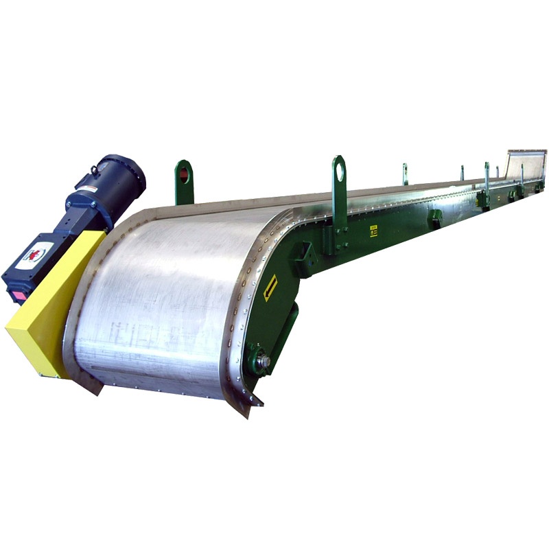
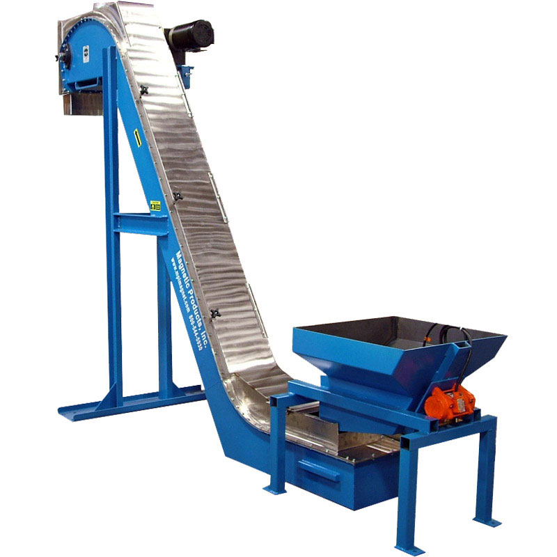
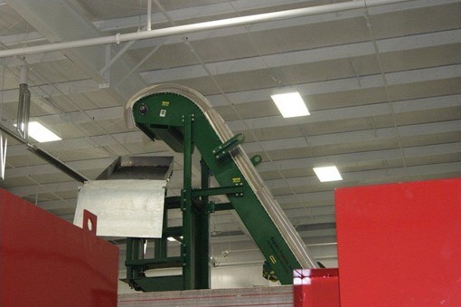
Description
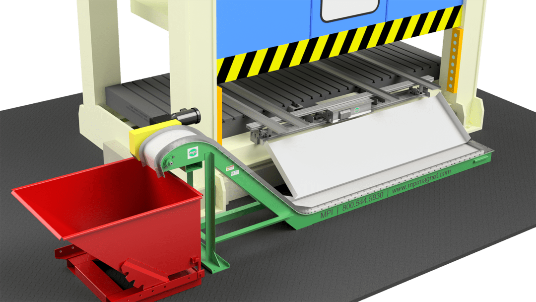
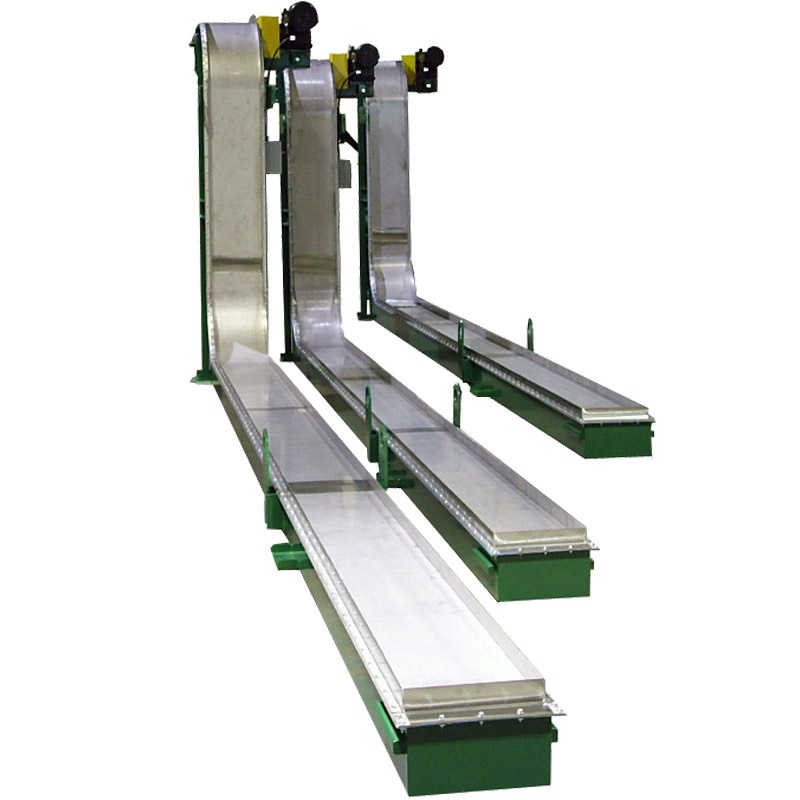
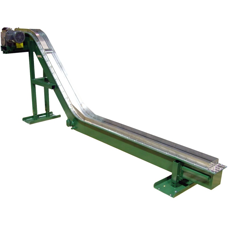
MPI’s Beltless Magnetic Conveyors (BLM) are designed to provide positive control of ferrous metal materials. BLM series conveyors are available in five (5) standard models in a wide range of configurations designed specifically to meet your application.
Typical materials conveyed include metal, stampings, turnings, chips, fasteners and scrap.
BLM conveyors are offered with many design options and can also be supplied with other ancillary components, such as feeders, hoppers, etc., to provide a complete material handling system.
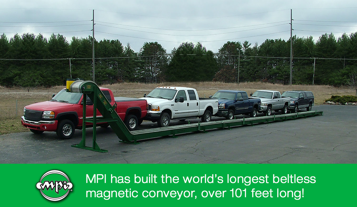
Conveyors are available in dogleg; dogleg with extended discharge; horizontal straight; and incline straight.